

Visual inspection (VT) is the direct examination of an asset’s surface using the naked eye, optical aids, or remote imaging systems to detect discontinuities, deterioration, or non-conformances — and it is the most fundamental method in non-destructive testing (NDT). ASNT confirms that VT is the simplest NDT method and typically serves as the first inspection step before any other technique is deployed. Three authorities govern competency and procedure in the UK context: BINDT (British Institute of Non-Destructive Testing), ISO 17637 / BS EN ISO 17637 for visual testing of fusion-welded joints, and ASNT for broader NDT certification frameworks.
Quick orientation before you read further:
- Maintenance checks: VT identifies corrosion, cracking, and mechanical damage during routine plant walk-downs.
- Incoming quality control: surface defects, coating failures, and dimensional non-conformances are caught at goods-in before components enter production.
- Failure analysis: post-incident VT establishes the visible origin and extent of damage before destructive examination begins.
One published electronics inspection study, cited on Wikipedia’s visual inspection entry, reported a false-negative rate of approximately 23% and a false-positive rate of approximately 2% under controlled conditions — figures that illustrate why VT alone is rarely sufficient for safety-critical decisions and why escalation criteria matter.
Key takeaways
Visual inspection is the first-line NDT method in every well-run maintenance programme, and its reliability depends on standardised lighting, documented acceptance criteria, and systematic CMMS integration rather than inspector skill alone.
| Point | Details |
|---|---|
| VT is the NDT entry point | Use visual inspection first; escalate to UT, RT, or PT when findings are ambiguous or safety-critical. |
| Lighting determines detection | Target 500–1,000 lux with raking light at 15–30° to the surface; poor lighting is the primary cause of false negatives. |
| False negatives are measurable | One electronics study reported a false-negative rate of approximately 23%; calibration exercises and written acceptance criteria reduce this. |
| Standards and certification matter | Reference BS EN ISO 17637 for weld VT; certify inspectors to PCN/ISO 9712 Levels I–III via BINDT. |
| Fullyops closes the loop | Fullyops connects inspection findings to automated work orders and analytics dashboards, reducing time-to-repair and building a traceable asset history. |
Table of Contents
- What does visual inspection actually cover?
- How does visual inspection fit inside a formal NDT programme?
- What are the main visual inspection methods?
- What tools and lighting give you the most accurate results?
- How do you conduct a visual inspection step by step?
- What are the advantages and limitations of visual inspection?
- Which standards and certifications apply in the UK?
- How do you set up a visual inspection programme?
- What can automated visual inspection and AI reliably deliver?
- Where is visual inspection used across industries?
- A practical checklist for reliable visual inspections
- What drives the time and cost of a visual inspection?
- How do you measure inspection programme performance?
- How do you integrate visual inspection results into a CMMS?
- What the data tells you that most programmes ignore
- Fullyops turns inspection findings into closed work orders
- Sources
- FAQ
What does visual inspection actually cover?
Visual inspection is a surface method. It detects discontinuities that are open to, or visible at, the surface; it cannot reveal sub-surface flaws without supplementary techniques. Understanding that boundary is what separates a well-designed NDT programme from one that creates a false sense of assurance.
Defects VT can reliably detect:
- Surface cracks and crazing (fatigue, stress-corrosion, thermal)
- Corrosion, pitting, and general material loss
- Weld porosity, undercut, overlap, and incomplete fusion at the surface
- Misalignment, distortion, and dimensional non-conformance
- Coating failures: blistering, delamination, and holiday defects
- Foreign-object contamination and mechanical damage
Where VT reaches its limits and other NDT methods take over:
- Ultrasonic testing (UT): sub-surface volumetric flaws, wall-thickness measurement, and lamination detection — escalate when surface VT shows no defect but operating data suggests internal degradation.
- Radiographic testing (RT): internal porosity, inclusions, and weld root defects invisible to the eye — typically invoked for pressure-vessel welds after VT acceptance.
- Liquid penetrant testing (PT): surface-breaking cracks too fine for the naked eye — PT is the natural next step when VT raises suspicion but cannot confirm crack morphology. NASA’s penetrant testing guidance notes that fluorescent penetrant and UV techniques are used alongside VT precisely to highlight defects that normal light cannot resolve.
- Eddy-current testing (ET): near-surface flaws in conductive materials, particularly in aerospace tubing and heat-exchanger tubes.
The practical rule: use VT first because it is fast and cheap, then escalate to the appropriate volumetric or surface-enhancement method when VT findings are ambiguous or when the consequence of a missed defect is high.
How does visual inspection fit inside a formal NDT programme?
VT is not a standalone activity — it is the entry point to a structured decision tree. A well-run NDT programme treats every VT finding as either a pass, a conditional pass with monitoring, or a trigger for escalation.
A simplified decision flow:
- Step 1 — Conduct VT against documented acceptance criteria (e.g. maximum allowable crack length, corrosion depth, or coating holiday size per the relevant standard).
- Step 2 — Compare findings to acceptance criteria. Findings within tolerance: record and close. Findings at or beyond tolerance: flag for escalation.
- Step 3 — Escalate to UT, RT, PT, or ET depending on the suspected defect type and the asset’s criticality classification.
- Step 4 — Update the sampling plan. A cluster of VT rejections in one zone should increase inspection frequency or trigger a full-area scan.
BS EN ISO 17637 sets the procedural framework for visual testing of fusion-welded joints and defines acceptance levels that feed directly into this decision flow. BINDT’s practitioner guidance reinforces how those acceptance levels translate into practical inspector judgement at Levels II and III. VT findings also inform sampling plans: a clean VT record over several inspection cycles can justify a reduced sampling frequency, while repeated findings justify tightening it.
What are the main visual inspection methods?
Three principal modes exist: direct visual inspection (DVI), remote visual inspection (RVI), and automated visual inspection (AVI). Choosing between them depends on access, hazard level, required resolution, and production throughput.
1. Direct visual inspection (DVI)
The inspector examines the surface unaided or with hand-held optical aids (magnifiers, loupes, mirrors). DVI is the default for accessible surfaces where the inspector can position themselves within a comfortable working distance — typically within 600 mm and at an angle no less than 30° to the surface per standard VT guidance.
Best for: routine plant walk-downs, weld inspection on open structures, incoming goods checks, and post-maintenance verification.
2. Remote visual inspection (RVI)
RVI uses optical or electronic instruments to inspect surfaces the inspector cannot physically reach. The main tools are:
- Rigid borescopes: fixed-angle optics for engine cylinders, valve bores, and confined pipe interiors.
- Flexible videoscopes: articulating camera probes for turbine blade inspection, heat-exchanger tubes, and complex pipework.
- Drones (UAVs): external inspection of storage tank roofs, flare stacks, wind turbine blades, and bridge soffits where scaffolding would be prohibitively expensive or hazardous.
Best for: confined spaces, elevated or hazardous environments, and assets where access preparation (scaffolding, shutdown) would cost more than the inspection itself.
3. Automated visual inspection (AVI) / machine vision
AVI uses cameras, structured lighting, and image-processing algorithms — increasingly incorporating AI-based defect classifiers — to inspect surfaces at production speed. A high-speed PCB line, for example, can pass hundreds of boards per minute through an AVI station that flags solder defects for human review.

Best for: high-volume, repeatable inspection tasks where defect types are well-defined and a labelled training dataset exists.
Decision guidelines at a glance:
- Access restricted or hazardous → RVI (borescope or drone)
- High throughput, repeatable defect types → AVI
- Novel or ambiguous anomalies, low volume → DVI
- Safety-critical weld acceptance → DVI with documented acceptance criteria per ISO 17637
What tools and lighting give you the most accurate results?
Lighting and optics are where most manual inspection accuracy is won or lost. ASNT’s VT guidance identifies viewing distance, angle, and illumination as the primary determinants of detection reliability — not inspector experience alone.
Tool selection
- Hand magnifiers (×2–×10): general surface examination and weld bead assessment.
- Jeweller’s loupes (×10–×20): fine crack detection and coating defect characterisation.
- Inspection mirrors: angled surfaces, pipe backs, and weld roots in tight joints.
- Rigid borescopes: bores, cylinders, and short straight runs.
- Flexible videoscopes: articulating probes for turbine internals and complex pipework.
- Drones with HD/thermal cameras: large external surfaces, elevated structures.
- DSLR or mirrorless cameras with macro lenses: photographic evidence capture with controlled depth of field.
- Tripod rigs: consistent framing and repeatable photography for trend comparison.
Lighting guidance
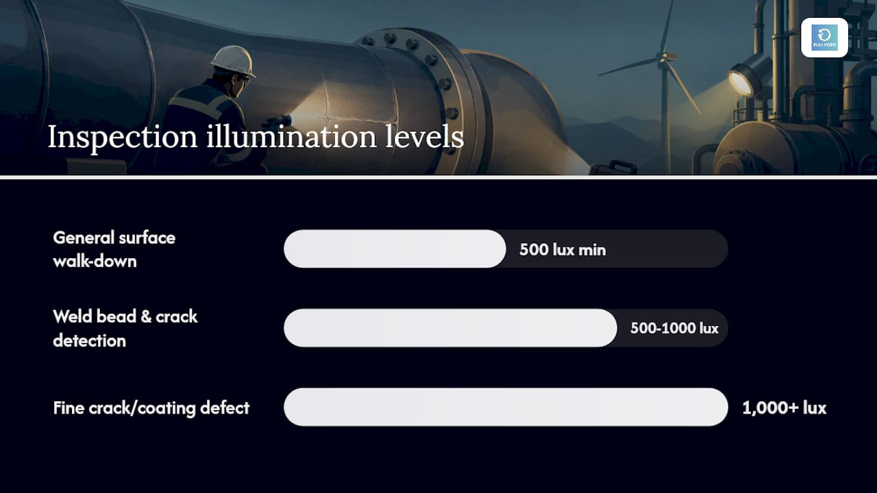
Industry guidance from Inspenet cites a recommended illumination range of approximately 500–1,000 lux for detailed visual inspection tasks, with higher lux appropriate for small features or low-contrast surfaces.
| Inspection task | Recommended illumination | Light type |
|---|---|---|
| General surface walk-down | 500 lux minimum | White LED torch or panel |
| Weld bead and crack detection | 500–1,000 lux | Directional LED, angled 15–30° |
| Fine crack or coating defect | 1,000 lux+ | Collimated or polarised light |
| Fluorescent penetrant (PT) | UV-A, darkened area | UV lamp, ≥1,000 µW/cm² |
Pro Tip: Angle your light source at 15–30° to the surface rather than perpendicular. Raking light throws shadows across surface discontinuities, making fine cracks and pitting visible that flat-on illumination completely misses.
Additional lighting considerations:
- Use a dark or neutral background behind translucent specimens to improve contrast.
- Polarised filters reduce glare on reflective metallic surfaces.
- UV/fluorescent techniques (per NASA PT guidance) enhance defect visibility on welds and corrosion-prone surfaces when standard white light is insufficient.
- Always verify that portable lamps meet the lux specification at the working distance, not just at the lamp face.
Safety note: UV lamps require appropriate eye protection (UV-blocking goggles) and skin protection. Drones operating near live plant must comply with UK Civil Aviation Authority (CAA) regulations and site-specific permit-to-work requirements.
How do you conduct a visual inspection step by step?
A repeatable inspection process reduces inspector-to-inspector variability and produces evidence that withstands audit scrutiny. The following workflow can be adapted into a site SOP.
-
Planning and risk assessment. Define the scope (asset ID, inspection zone, defect types of interest), reference the applicable standard (e.g. ISO 17637 for welds), confirm acceptance criteria, and complete a pre-task risk assessment covering access, PPE, and permit-to-work requirements.
-
Access and surface preparation. Remove loose scale, dirt, and coatings where the standard requires bare-metal examination. Verify that the surface temperature is within the acceptable range for the inspection method. Confirm adequate lighting is in place and measure lux at the working surface.
-
Equipment check and calibration. Verify that optical aids are clean and undamaged, that lamps meet the specified lux output, and that any measuring tools (gauges, rulers) are within calibration. SafetyCulture’s inspection guidance recommends defining acceptance criteria and verifying equipment before beginning any inspection.
-
Systematic observation. Work in a defined pattern (e.g. left-to-right, zone-by-zone) to avoid missed areas. Vary the viewing angle and light angle as you progress. Maintain a working distance appropriate to the optical aid in use — for unaided inspection, within 600 mm at no less than 30° to the surface is standard VT practice.
-
Measurement and characterisation. For any indication found, record: location (reference to a datum or weld seam), orientation (longitudinal, transverse, circumferential), approximate dimensions (length, width, depth if measurable), and severity classification against the acceptance criteria.
-
Photographic documentation. Capture at minimum: one orientation shot showing the indication in context, one close-up with a scale reference (ruler or calibrated scale card), and one shot with raking light if the defect is a surface crack. Name files using a consistent convention:
[AssetID]_[Date]_[Zone]_[SeqNo].jpg. Record EXIF data (date, time, GPS if applicable) and note the camera settings used. -
Immediate actions. If a finding exceeds acceptance criteria, raise a non-conformance record immediately. Do not defer documentation to the end of the shift.
-
Report completion. The inspection report should capture: inspector name and certification level, date and time, environmental conditions (temperature, humidity, lighting lux), equipment used, findings with photo references, acceptance/rejection decision, and recommended follow-up action.
Sample report minimum fields:
- Asset ID and description
- Inspection standard and acceptance criteria reference
- Inspector name, certification level, and signature
- Date, time, and environmental conditions
- Equipment and lux level recorded
- Finding location, orientation, dimensions, and severity
- Photo file references
- Pass/fail decision and recommended action
What are the advantages and limitations of visual inspection?
VT’s speed and accessibility make it the default first-line method across virtually every industry. Its limitations are equally well-documented and must be managed through procedure, not ignored.
Advantages:
- Cost-effective: minimal capital equipment for DVI; no consumables beyond PPE and lighting.
- Immediate results: findings are available in real time, enabling rapid decision-making.
- Versatile: applicable to metals, composites, coatings, welds, and mechanical assemblies across manufacturing, oil and gas, power generation, aviation, and civil infrastructure.
- Non-invasive: no coupling medium, radiation, or chemical agents required for basic DVI.
- First-line efficiency: a clean VT record can eliminate the need for more expensive volumetric testing on low-risk assets.
Limitations:
- Surface-only detection: sub-surface defects are invisible to VT regardless of inspector skill.
- Inspector variability: detection reliability depends on training, fatigue, lighting, and access quality. This is the primary source of false negatives.
- Environmental sensitivity: poor lighting, surface contamination, restricted access, and extreme temperatures all degrade performance.
- Resolution limits: fine cracks below approximately 0.1 mm width are typically beyond unaided visual resolution without optical aids.
- Subjectivity in borderline cases: acceptance/rejection decisions near the tolerance boundary vary between inspectors without rigorous calibration.
One published electronics inspection study reported a false-negative rate of approximately 23% — meaning roughly one in four defects was missed — alongside a false-positive rate of approximately 2% in that specific integrated-circuit inspection context. These figures come from a narrow, controlled study and should not be applied universally, but they illustrate the scale of variability that standardised lighting protocols and inter-inspector calibration exercises are designed to reduce.
Which standards and certifications apply in the UK?
UK inspectors operate within a layered framework of international standards and national certification schemes. Knowing which document governs which task is a prerequisite for producing auditable inspection records.
Key standards:
- BS EN ISO 17637: the primary standard for visual testing of fusion-welded joints in metallic materials. It defines inspection conditions, acceptance levels, and report content. Any weld VT in a UK pressure-vessel, structural steel, or pipeline context should reference this standard.
- BS EN ISO 9712: specifies qualification and certification requirements for NDT personnel across all methods, including VT, and is the basis for most UK employer competency frameworks.
- PD CEN/TR 16748: a CEN technical report providing supplementary guidance on visual testing techniques and equipment.
- BINDT guidance documents: BINDT’s practitioner forum and technical notes provide Level II/III-focused procedural detail and are widely used as the UK reference for VT competency expectations.
Certification levels (VT):
- Level I: performs VT under supervision; follows written procedures; records findings.
- Level II: sets up and calibrates equipment; interprets and evaluates results; prepares written procedures; supervises Level I personnel.
- Level III: develops and approves procedures; interprets standards; responsible for the NDT programme.
ASNT’s SNT-TC-1A and CP-189 documents provide a parallel US-origin framework that many multinational operators reference alongside ISO 9712. Where a UK client specifies ASNT certification, inspectors typically hold PCN (Personnel Certification in NDT) from BINDT as the primary UK credential and ASNT qualification as a supplementary endorsement.
Practical recordkeeping for audits:
- Retain calibration certificates for all optical and lighting equipment.
- Keep a training and competency matrix showing each inspector’s certification level, expiry date, and continuing professional development (CPD) record.
- Link inspection reports to the relevant standard and acceptance criteria version. A maintenance compliance checklist that maps inspection records to audit requirements can significantly reduce preparation time before a third-party audit.
How do you set up a visual inspection programme?
A programme is more than a schedule. It needs defined procedures, acceptance criteria, staffing, and a recordkeeping system that produces evidence rather than just activity.
SOP essentials (who, what, when, how, and accept/reject):
- Who: minimum certification level per task (e.g. Level II for weld acceptance per ISO 17637); named responsible person for programme oversight.
- What: asset register with inspection scope per asset type; defect catalogue with acceptance criteria referenced to the applicable standard.
- When: inspection frequency linked to criticality classification (safety-critical, production-critical, or non-critical) and to operating hours, cycles, or calendar intervals.
- How: written inspection procedure per asset type, specifying method, equipment, lighting, access requirements, and reporting format.
- Accept/reject: explicit pass/fail criteria with no ambiguous middle ground; escalation path for borderline findings.
Sampling and frequency guidelines:
- Classify assets by criticality (safety, production, cost).
- Set baseline inspection intervals from the manufacturer’s recommendation or applicable standard.
- Adjust frequency upward when VT findings cluster in a zone or when operating conditions change (increased load, new process fluid, temperature excursion).
- Reduce frequency only after a documented clean record over a defined number of inspection cycles, with sign-off from the Level III or engineering authority.
Recordkeeping checklist:
- Inspection report with all mandatory fields completed (see process steps section above).
- Photo files stored in a named folder structure linked to the asset ID.
- Non-conformance records with disposition (repair, monitor, replace, or accept-as-is with engineering justification).
- Corrective action records with close-out evidence.
- Inspector competency records cross-referenced to each report.
For compliance-focused programmes, a structured maintenance checklist that maps each inspection task to its governing procedure reduces variation and provides a ready audit trail.
What can automated visual inspection and AI reliably deliver?
Automated visual inspection (AVI) and AI-based defect detection have moved well beyond pilot projects in high-volume manufacturing. Understanding what they deliver reliably — and where they fail — is what separates a successful deployment from an expensive disappointment.
Where AVI adds clear value:
- High-speed production QA: PCB solder inspection, pressed-metal part checking, and label/packaging verification at line speed.
- Repeatable dimensional checks: gap measurement, surface finish grading, and colour/shade consistency.
- Trend detection in maintenance: camera-equipped drones or fixed cameras on rotating equipment can flag progressive surface deterioration between manual inspection cycles.
Inspenet’s technical guidance notes that AI and machine vision reduce operator variability and increase throughput in repeatable, high-volume tasks, but require robust labelled datasets and ongoing model validation. That last point is where most pilots stall.
Pilot deployment checklist:
- Data collection: gather a representative image set covering all expected defect types, lighting conditions, and surface states — typically hundreds to thousands of labelled examples per defect class.
- Labelling: use certified inspectors (Level II minimum) to label the training set; label quality directly determines model quality.
- Edge vs cloud inference: edge inference (on-device GPU) suits production lines where latency matters; cloud inference suits lower-frequency inspection with larger image files.
- Acceptance criteria: define the minimum detection rate and maximum false-negative rate the model must achieve before going live; validate against a held-out test set.
- Fallback procedure: specify the manual inspection protocol that activates when the model confidence falls below threshold or when the system flags an anomaly it cannot classify.
Manual vs assisted vs fully automated: practical trade-offs
A technical overview of the three modes confirms that hybrid approaches are common in modern facilities, pairing manual inspection for ambiguous or novel anomalies with automated checks for repeatable pattern detection.
- Manual DVI: low capital cost, flexible for novel defects, high variability between inspectors, limited throughput.
- Assisted (AVI with human review): reduces variability, flags candidates for human decision, moderate capital cost, requires model maintenance.
- Fully automated AVI: highest throughput, lowest per-unit cost at scale, requires extensive training data, poor performance on novel defect types, significant upfront investment.
Where is visual inspection used across industries?
VT applies wherever a surface can be examined, but the specific methods, defects, and hazards vary considerably by sector.
-
Manufacturing: incoming goods inspection (castings, forgings, machined parts), in-process weld checks, final assembly verification. AVI is common on high-volume press and assembly lines. Typical defects: surface cracks, porosity, dimensional non-conformance, coating holidays.
-
Oil and gas: pressure vessel and piping inspection during turnarounds, storage tank floor and roof surveys (drone RVI increasingly standard), flare stack and riser external inspection. Typical defects: corrosion, pitting, weld defects, mechanical damage. Environment-specific hazard: confined space entry and ATEX-rated equipment requirements.
-
Power generation: turbine blade inspection (flexible videoscope RVI), boiler tube and heat-exchanger inspection, transformer and switchgear visual checks. Typical defects: erosion, cracking, fouling, insulation damage.
-
Aviation: airframe skin inspection for corrosion and impact damage, engine borescope inspection between overhauls, landing gear and control surface checks. Governed by EASA and CAA Part-145 requirements in the UK.
-
Civil infrastructure: bridge deck and soffit inspection (drone RVI), concrete crack mapping, structural steel corrosion surveys, tunnel lining assessment. Typical defects: spalling, cracking, delamination, section loss.
For HVAC and building services, a field service management checklist adapted to the specific asset type provides a practical starting point for structuring inspection rounds.
A practical checklist for reliable visual inspections
This checklist is designed for field use and can be incorporated directly into a site SOP or a digital work order.
Pre-inspection:
- Confirm asset ID, inspection scope, and applicable standard.
- Complete risk assessment and obtain permit-to-work if required.
- Verify inspector certification level is appropriate for the task.
- Check and clean all optical aids; measure lux at the working surface.
- Confirm surface preparation meets the standard’s requirements.
During inspection:
- Work in a systematic pattern; do not skip zones.
- Vary light angle (15–30° raking) and viewing angle for each zone.
- Use magnification appropriate to the expected defect size.
- Measure and characterise every indication before moving on.
- Photograph every finding with scale reference and raking light.
Post-inspection:
- Complete the inspection report before leaving the work area.
- Raise non-conformance records immediately for out-of-tolerance findings.
- Store photos in the agreed folder structure with the correct naming convention.
- Update the asset’s inspection history in the CMMS.
Pro Tip: Run a quarterly peer-calibration exercise: two inspectors independently examine the same prepared test piece with known seeded defects, then compare findings. Disagreements reveal training gaps and lighting protocol drift before they affect real assets.
Continuing competence:
- Refresher training at intervals specified by the certification body (typically every five years for PCN recertification, with annual CPD evidence).
- Periodic cross-checks: compare VT findings against UT or PT results on the same area to validate detection rates.
- Maintain a personal log of inspection hours by method and asset type.
What drives the time and cost of a visual inspection?
Cost and duration vary enormously depending on access complexity, equipment, and reporting requirements. Understanding the drivers helps managers build realistic budgets and justify AVI investment.
Primary cost drivers:
- Access preparation: scaffolding, rope access, confined-space entry, or drone mobilisation can dwarf the inspection cost itself.
- Surface preparation: cleaning, decoating, or temperature conditioning adds time and consumable cost.
- PPE and safety compliance: ATEX-rated equipment, respiratory protection, and confined-space rescue standby all carry direct costs.
- Optical equipment: videoscope hire or drone mobilisation adds day-rate costs for RVI.
- Inspector grade: Level II and III inspectors carry higher day rates than Level I.
- Image handling and reporting: structured photo documentation and formal report writing can add 30–60 minutes per inspection event.
Typical time estimates by inspection type:
- Routine DVI walk-down (accessible plant, 10–20 items): 1–3 hours including report.
- RVI with flexible videoscope (single turbine or heat-exchanger): 2–4 hours plus mobilisation.
- Drone external survey (storage tank roof or bridge span): 1–2 hours flight time plus 2–4 hours data review and reporting.
- AVI line scan (per production shift, once commissioned): near-zero marginal time per unit.
Cost reduction without sacrificing detection quality:
- Pre-clean surfaces before the inspector arrives to eliminate preparation time on the day.
- Batch inspections: group assets in the same zone into a single access event.
- Use risk-based sampling to focus detailed inspection on high-criticality or high-history assets.
- Invest in standardised lighting rigs that can be repositioned quickly rather than improvising each time.
How do you measure inspection programme performance?
A programme without KPIs cannot be improved. The following metrics give maintenance managers a quantitative basis for programme review.
| KPI | Definition | Target (indicative) |
|---|---|---|
| Detection rate | Confirmed defects found / total defects present (from seeded or cross-check set) | High for safety-critical assets |
| False-negative rate | Defects missed / total defects present | ≤10% for safety-critical assets |
| Inter-inspector agreement | % of findings where two inspectors reach the same accept/reject decision | High |
| Time per inspection | Elapsed time from start to signed report | Baseline then trend |
| Non-conformance close-out rate | NCRs closed within target period / total NCRs raised | High within defined SLA |
Measurement methods:
- Blind re-inspection: a second inspector examines the same asset without access to the first inspector’s findings; compare results to calculate agreement rate.
- Seeded defects: introduce known artificial defects (e.g. EDM notches, calibrated corrosion coupons) into the inspection population; track detection rate over time.
- Statistical sampling: periodically follow up VT with UT or PT on a random sample of passed items to estimate the false-negative rate in production conditions.
- Cross-method validation: compare VT findings against UT C-scan or PT results on the same weld seam to calibrate inspector acceptance decisions.
A well-run programme with standardised lighting, peer calibration, and documented acceptance criteria should achieve substantially lower rates on comparable tasks.
How do you integrate visual inspection results into a CMMS?
Inspection evidence that stays in a paper file or a shared drive folder does not drive maintenance decisions. The integration workflow below maps VT outputs into a CMMS so findings automatically generate work orders, update asset histories, and feed reporting dashboards.
Integration workflow:
- Capture: inspector completes the digital inspection form on a mobile device (online or offline), attaches photos with the agreed naming convention, and records defect codes and severity levels.
- Tag: each finding is tagged with the asset ID, GPS or location reference, inspection date, and inspector ID.
- Upload: the completed form and photo files sync to the CMMS when connectivity is restored (offline-first capture is critical for confined-space and remote-site inspections).
- Auto-create work order: findings above the defined severity threshold automatically generate a corrective work order, pre-populated with the asset ID, defect description, photo references, and recommended action.
- Assign: the work order is routed to the appropriate technician or contractor based on skill set and availability.
- Close with evidence: the technician attaches post-repair photos and completes the work order; the asset history is updated with the repair record linked to the originating inspection finding.
Field mapping essentials:
- Photo filename:
[SiteCode]_[AssetID]_[YYYYMMDD]_[Zone]_[SeqNo].jpg - Defect codes: standardised taxonomy (e.g. CR = crack, CO = corrosion, WD = weld defect, MD = mechanical damage)
- Severity levels: 1 (monitor), 2 (plan repair within 30 days), 3 (immediate action)
- Required CMMS fields: asset ID, inspection standard, inspector ID, finding description, defect code, severity, photo file reference, accept/reject decision
Implementation tips:
- Configure alert thresholds so that severity-3 findings trigger an immediate notification to the maintenance manager.
- Build a reporting dashboard that shows open NCRs by asset, zone, and defect type — this surfaces repeat-failure patterns that individual work orders obscure.
- Review asset lifecycle management guidance to understand how inspection outputs feed lifecycle replacement decisions, not just immediate repairs.
What the data tells you that most programmes ignore
It does not mean that a quarter of your defects are being missed right now. What it means is that without a documented lighting protocol, a calibrated acceptance-criteria document, and a periodic peer-calibration exercise, there is no reason to assume your programme performs better than that baseline.
The practical implication is straightforward: the first week’s investment in any inspection programme should go into standardising the lighting rig and the photo protocol, not into buying more sophisticated equipment. A videoscope does not help if the inspector is working under a 200-lux torch and making accept/reject calls from memory rather than from a written acceptance criteria sheet.
Every false positive generates a work order, consumes a technician’s time, and, if repeated, erodes inspector credibility with the maintenance team. Reducing false positives requires the same intervention as reducing false negatives: clear, written acceptance criteria with reference images for borderline cases.
The programmes that perform consistently well share one characteristic: they treat VT as a system, not a skill. The inspector’s eye is one component. The lighting, the procedure, the acceptance criteria, the calibration exercise, and the CMMS integration are the others. Remove any one of them and the system degrades.
Fullyops turns inspection findings into closed work orders
Conducting a thorough visual inspection is only half the job. The other half is making sure every finding reaches the right technician, gets resolved within the agreed timeframe, and leaves a traceable record in the asset history. That is precisely where many programmes lose value: findings are documented on paper or in a shared folder, and the link between the inspection report and the corrective action is manual, slow, and easy to lose.
Fullyops connects inspection evidence directly to your work order management process, so a severity-3 finding raises a corrective work order automatically, routes it to the right technician, and closes with photo evidence attached. Your operations analytics dashboard then surfaces repeat-failure patterns across assets, sites, and inspection cycles — turning individual findings into programme-level intelligence. The platform supports offline data capture for confined-space and remote-site inspections, custom defect codes, severity thresholds, and configurable alert rules. Book a demo to see how Fullyops maps to your existing inspection workflow.
Sources
The following references are the primary sources for standards, certification, and technical guidance cited throughout this guide.
- Visual Testing (VT) Method for NDT Inspections
- Visual Inspection: An In-Depth Guide New for 2026
- Visual Inspection: Techniques, Innovations and Applications
- Visual inspection
- Visual Inspection, Part 1
Where to find certified training in the UK:
FAQ
What is meant by visual inspection?
Visual inspection is the examination of an asset’s surface using the naked eye, optical aids, or remote imaging systems to detect discontinuities, deterioration, or non-conformances. It is the most fundamental NDT method and typically serves as the first step before any other technique is applied.
What are the steps in a visual inspection?
The core steps are: plan and risk-assess; prepare access and surface; verify equipment and lighting; observe systematically with varied light and viewing angles; measure and characterise findings; photograph with scale references; and complete the inspection report with accept/reject decisions before leaving the work area.
How accurate is a visual inspection?
Accuracy depends heavily on lighting, procedure, and inspector calibration.
Should you start cleaning with a visual inspection?
Yes. A preliminary visual check before cleaning identifies loose contamination, active corrosion, or mechanical damage that cleaning might obscure or worsen. After cleaning, a second VT confirms the surface condition and establishes the baseline for acceptance or escalation.
Which certification body governs visual inspection in the UK?
BINDT (British Institute of Non-Destructive Testing) administers the PCN (Personnel Certification in NDT) scheme, which is the primary UK certification route for VT inspectors at Levels I, II, and III, aligned to BS EN ISO 9712.
Recommended
- Corrective maintenance steps: a guide for operations managers
- Inspection checklist for equipment: 2026 industrial guide
- Preventive maintenance examples to extend asset life